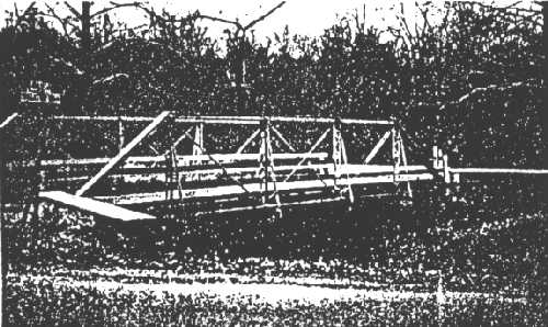
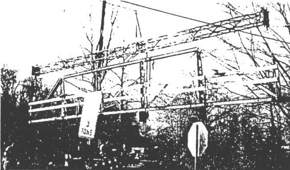
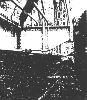
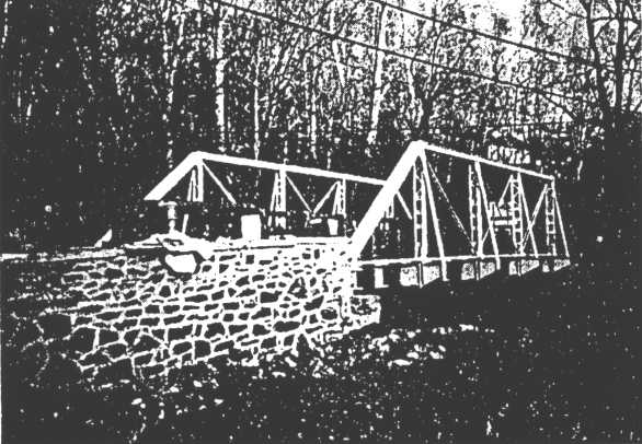
ELEVATION VIEW OF THE BRIDGE PRIOR TO CONSTRUCTION
This paper was published in the Proceedings from the Symposium on Practical Solutions for Bridge Strengthening and Rehabilitation, April 5-6, 1993, sponsored by the National Science Foundation and the Department of Civil and Construction Engineering at Iowa State University.
Investigation of section loss on a Chester County wrought iron truss built in 1889 found cracking in three truss pins, and prompted the bridge closing in 1991. The historical significance of the structure and its low traffic volume permitted a unique rehabilitation alternative. A steel girder bridge was designed and constructed on concrete abutments placed behind the existing stone masonry abutments. The trusses were reconditioned and aesthetically attached to the new girder bridge. The finished structure resembles the original truss bridge, yet serves as a new steel girder bridge.
Chester County Bridge 165, Chandler’s Bridge in East Marlborough Township, Pennsylvania was constructed in 1889 by John Denithorne and Sons, a local bridge building company from Phoenixville, Pennsylvania. The original construction was a wrought iron pony truss whose iron was forged locally at the Phoenix Iron Company also located in Phoenixville. The bridge was constructed for a public road leading from Kennett Square to London Grove, Pennsylvania. During the 1800’s, the adjacent property was known as Willow Glen Mills, a grist and saw mill. The property is currently a horse farm which houses four of the original buildings listed on the National Historic Register. There is significant local history associated with both the bridge and the surrounding property.
ELEVATION VIEW OF THE BRIDGE PRIOR TO CONSTRUCTION
Originally, County Bridge 165 consisted of simple span, pin connected pony trusses. The bridge span was 49’-6" clear and 52’-l" center to center of bearings. The trusses along with steel stringers and floorbeams were supported on stone masonry abutments. The structure originally had a timber plank deck, but this had been replaced by glue laminated timber panels and a bituminous wearing surface.
Bridge #65 is located over the West Branch of the Red Clay Creek, a stocked trout stream, requiring special scheduling and protective measures for construction along the stream. The hydraulic capacity of the bridge was greater than a 100 year flood; and the seventy-three degree skew of the structure provided good stream alignment, eliminating any significant bank erosion or undermining of the substructure.
The average daily traffic on the bridge was seventy-nine vehicles per day, counted in 1990. The bridge was originally constructed for horse and light vehicle traffic and was considered functionally obsolete for modern loadings. The bridge is located at an intersection, and modern criteria had designated it as one lane due to its narrow roadway width of fifteen feet. Structural ratings were very limiting for modern traffic conditions. The operating rating of the stringers and several truss members was slightly over 10 tons. The bridge was posted at 9 tons based on its condition and ratings, unfortunately, truck traffic in excess of the posted limits had been observed on the bridge. Also, the light construction of the bridge caused vibration under most live loads.
During a routine inspection in 1990, County inspection forces discovered extensive section loss of the truss pins at all four bearing areas and a fatigue crack at a welded railing connection. Rating calculations based on the section loss lowered the bridge operating rating to 8.08 tons and the inventory rating to 2.74 tons. The bridge was immediately reduced in posting from 9 to 3 tons and Jastrzebski Engineers, Inc. was commissioned to perform a feasibility study for the repair or replacement of the structure.
The feasibility study was based on traffic conditions, economic considerations, and the historic and aesthetic concerns associated with County Bridge #65.
As a part of the study, the truss pins were ultrasonically tested in March of 1991 by Valley Forge Laboratories. All twelve of the 2" diameter bottom chord pins were evaluated. The pins were tested using a 112" to 1" diameter, 2.25 MHz transducer which produced longitudinal sound waves. The equipment was calibrated prior to testing by using a standard IIW calibrated block and a 14" section of steel round stock. Scanning levels and references were determined through the calibration process with back reflection set at 100% of the screen width. Any discontinuities found in the truss pins would cause a loss of back reflection. Total loss of back reflection and an additional signal equal in amplitude to the original back reflection would occur at pin locations where there was full width cracking. Eleven of the truss pins produced signals which indicated a reduction in overall exterior section of the pins. Minor losses in back reflection were observed in these pins and was attributed to their irregular material composition.
Pin #3, located midspan in the upstream bottom chord, had similar sidewall signals indicating similar exterior section loss; however, it also revealed a signal which covered 100% of the test surface. This signal indicated a large discontinuity in the pin at a depth of approximately five inches into the pin. The signal varied in amplitude relative to the backwall signal and there was not a full loss of back reflection at any point. This suggested a planar discontinuity over the full cross section of the pin without complete separation. Jastrzebski Engineers, Inc. suggested this problem was a recent development perhaps caused by a single overloaded vehicle. If the crack had existed for an extended period of time, complete separation would have been likely due to the impact loading on the bridge and vibration caused by its light construction.
Bridge #65 was a fracture critical structure where the failure of any one member could create the collapse of the entire structure. Therefore, the bridge was immediately closed to traffic on the day of testing. The section loss discovered in the 1990 bridge inspection had previously downgraded the truss pins as the controlling members for the bridge ratings. The further discovery of a planar discontinuity in a bottom chord pin confirmed that the bridge was no longer safe for vehicular traffic. The feasibility study and an impending design were given high priority to accommodate an expeditious bridge opening.
In February 1991, the County met with Jastrzebski Engineers, Inc. to review the studied alternatives. The County had originally requested a repair to upgrade the structure to a 20 ton live load capacity, which could accommodate school buses, emergency vehicles and most local delivery trucks. Jastrzebski Engineers, Inc. concluded that to achieve a 20 ton rating every member of the existing structure would require reinforcement or replacement. The uncertainty of the physical and metallurgical properties of the iron limited the reinforcement options, thereby suggesting replacement of each member, an impractical and cost prohibitive alternative.
A second alternative was to repair and upgrade the structure to a 15 ton live load capacity. Most of the primary structural members could be re-used and the life of the repaired bridge would be 15 to 20 years. The existing deck could be replaced with a steel grid deck to reduce dead load and to provide a greater load carrying capacity. New steel stringers, new bearing pins and bottom chord pins, new bearings, and new hangers could replace the existing members. New cables could be installed along the bottom chord for redundancy. The cost of this option was more reasonable; but the capacity and life of the rehabilitated structure was less than desired, and complications in construction were expected.
The third and final option from the feasibility study was to completely replace the bridge with a new concrete structure. This was the most cost effective solution and was the recommended alternative.
The County Engineer’s office working in conjunction with the Historic Preservation office reviewed the proposed alternatives. The construction of a new bridge was not preferred due to the historicity of the bridge and its surroundings. Also, funding was not immediately available for new bridge construction. Repairing and strengthening the bridge to a 15 ton rating was the most preferred alternative, however, the county anticipated difficulty in disassembling the trusses for replacement of members, and the life expectancy of this repair was limited. The first option was cost prohibitive for the load carrying capacity of the completed structure.
Further discussion of the project with Jastrzebski Engineers, Inc. established a fourth option whereby a new steel structure could be built within the aesthetic shell of the old bridge. The County reviewed this proposal with the Historic Preservation Office and commissioned Jastrzebski Engineers, Inc. to design the new bridge.
The proposed design retained the architectural integrity of the truss bridge yet increased the live load capacity in excess of 20 tons. The low average daily traffic and good sight distance precluded the need to increase the roadway width. Also, maintaining the existing roadway width eliminated the need for right of way negotiation and acquisition, an often timely process.
The rehabilitation design included the restoration of the trusses, the construction of concrete stub abutments behind the existing stone masonry abutments, the placement of new steel girders and the placement of a steel grid deck with a timber plank wearing surface. The new abutments, steel stringers and grid deck serve as the structural members and provide a 20 ton load carrying capacity. The original stone abutments, the trusses and a new timber wearing surface are aesthetic features which conceal the girder bridge. The timber wearing surface was proposed also to prevent the hazards associated with a grid deck located at an intersection. The bridge is located in a rural area adjacent to a horse farm, therefore, a grid deck would be impractical since horses and other livestock will not cross an open deck. The County had reservations with the placement of a standard timber deck because of the limited life of exposed timber and the constant maintenance required. An acceptable alternative to this problem was to use Ekki, an African hardwood with the following characteristics:
| Average Unit Weight = 72 lbs / c.f. |
| Fire Resistance: | 10 minute test | 30 minute test |
| Thickness | 1 l/2" | 3" |
| Flame Spread Index | 0 | 10 |
| Smoke Value | 5 | 10 |
| Minimum Allowable Stresses: | Ekki |
| Bending | 3,750 psi |
| Tension | 3,450 psi |
| Compression parallel to grain | 3,550 psi |
| Compression perpendicular to grain | 2,000 psi |
| Shear parallel to grain | 425 psi |
| Modulus of elasticity | 2,490,000 psi |
Lophira Alata (Ekki’s botanical name) is a tree which grows to an approximate height of 150’ and a diameter of six feet. The wood is extremely durable with a life expectancy of greater than twenty-five years. It is naturally resistant to decay, insects, and fire without the use of chemical treatments or preservatives. Ekki is also a very attractive hardwood which when exposed to light darkens a deep reddish brown. For an aesthetic compliment to the Ekki timber deck and for its structural advantages, Ekki was chosen for the bridge and approach guiderail.
The rehabilitation design of Chester County Bridge #65 was structurally reviewed and approved by the Pennsylvania Department of Transportation, and the project was competitively bid through the County in the summer of 1992. Lenni Electric Corporation was awarded the project for a construction cost of $224,177.50, with 100% County Funding. Notice to proceed was September 17, 1992 and the project was awarded with 100 calendar days for completion.
Shop drawings for the Ekki timber details and the steel were prepared and approved during the first month of construction. The glue laminated bridge deck, timber wheel guards and the stringers were removed from the structure. At this point, it was critical to establish a method to carefully remove the trusses for reconditioning. Lenni Electric Corporation chose to transport the trusses to a shop for minor repairs and painting. Through their sub-contractor, Lenni developed a scheme for the removal and transport of the trusses. After several revisions, the scheme was accepted by Jastrzebski Engineers, Inc. and the disassembly of the trusses was begun.
The trusses had to be laterally braced before the removal of the floorbeams to prevent rotation of the trusses. Out of plane bending of the trusses could cause irreversible damage to the slender truss members. After the bracing was secured, ironworkers flame cut the floorbeams several feet from the trusses and removed them.
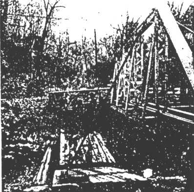
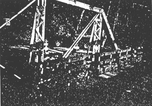
BRACING OF THE TRUSSES WAS REQUIRED PRIOR TO
REMOVAL OF THE FLOORBEAMS
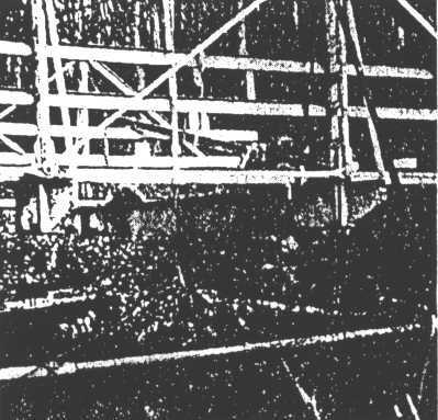
FLOORBEAMS WERE FLAME CUT AND CAREFULLY REMOVED
The trusses were loosely strapped at the verticals to provide additional lateral support. A continuous steel section was welded to the remaining floorbeam sections to provide support to the bottom truss chord. The modified channel section which had been welded to the original truss in the 1930’s as bridge rail was left in place for temporary support.
A 30 ton crane and a sixty foot spreader truss was used to pick each bridge truss at the bearings. The bearings had been shimmed and supported with steel plates.
A 30 TON CRANE WAS USED TO LIFT THE TRUSS FROM THE
ABUTMENTS
Both trusses were mounted upright on W sections at their bearings on a full deck low boy truck. A route was carefully chosen to avoid vertical and horizontal obstructions and the trusses were transported to the shop where the new steel was being fabricated. Upon arrival, the steel channel bridge rails were removed and the trusses were blasted to near white metal. The trusses were modified at the cut floorbeams to accommodate a bolted connection to the new steel girders. Several cracks on the diagonal members were repaired, and then the trusses were painted with a three coat paint system. The primer coat used was a self curing, inorganic zinc consisting of a basic zinc silicate complex. The intermediate coat was a two component, cross-linked epoxy and the top coat was a durable high gloss urethane. The County Engineer’s Office and the Historic Preservation Office chose tan as the final color of the truss and the new steel members. This is the most historically accurate color which compliments the timber details and allows visual steel fatigue inspection.
While the trusses were being reconditioned, Lenni excavated behind the existing stone masonry abutments and placed reinforced concrete stub abutments. These abutments were placed in the same skew as the original truss bridge. Care was taken to maintain the stability of the stone abutments during the excavation. Rock was placed along both abutments to provide scour protection, and the stone masonry was reset and pointed as required.
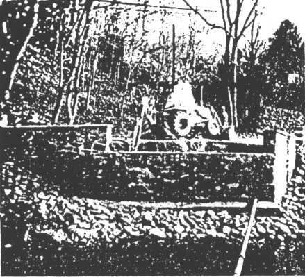
EXCAVATION BEHIND THE EXISTING STONE MASONRY WAS PERFORMED WITH
EXTREME CARE
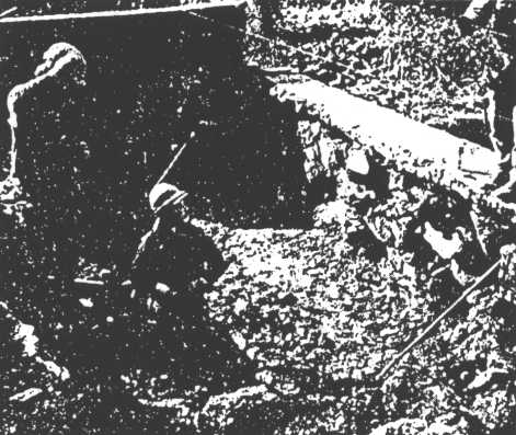
Once the new abutments were in place, the site was prepared for setting the new steel girders. Five 60’ Wl8xll9 steel girders were delivered to the site and set on the new reinforced concrete abutments. The steel was laterally supported in place by Wl8x35 diaphragms spaced to coincide with the original truss panels.

SETTING OF STEEL GIRDERS ON CONCRETE ABUTMENTS
LOCATED BEHIND ORIGINAL MASONRY
After reconditioning, the trusses were returned to the site; and in the same manner that they were removed, they were set on steel bearing plates cantilevered from the fascia beams. The remaining floorbeam sections were modified to bolt onto the fascia beams in line with the interior diaphragms. The camber in the girders and some movement of the trusses during transport required some minor shimming for an accurate fit.
WORKERS SET A TRUSS IN PLACE
TRUSS IS BOLTED TO STEEL GIRDERS
Once the trusses were mounted on the new steel, an open steel grid deck was welded to the girders. Paint on the grid deck was masked where welding was required; therefore, touch up painting was necessary before the timber wearing surface was installed. The winter weather required the contractor to place a tent over the entire structure to maintain a heated area for painting. Propane and kerosene heaters were used to maintain minimum curing temperatures inside the tent for the paint system.
THE BRIDGE WAS TENTED FOR WINTER PAINT TOUCH UP
An Ekki timber wearing surface was installed over the open steel grid deck for practical and aesthetic reasons. Two inch grooved planks were placed at the same skew as the bridge abutments. The grooves roughen the riding surface, a requirement since the bridge is located at an intersection.
The planks were secured with flathead bolts countersunk flush with the timber to eliminate any irregularities in the finished surface. The steel grid deck, combined with a timber wearing surface offers a light structurally sound deck with country appeal able to accommodate both vehicular and equestrian traffic.
GROOVED ERKI DECK PLANKS WERE INSTALLED OVER THE STEEL GRID DECK
To provide protection for the motorists and the historic trusses, timber bridge rail was installed. 6"x8" Ekki timber posts spaced at four foot intervals were bolted through spacer blocks to the steel girders. Two 4"x6" Ekki rails were bolted with round head bolts to the post to serve as structurally approved bridge rail. 6'x10" Ekki timber wheel guards where installed beneath the rails to define the curb line. Ten 2"x12" drainage scuppers were cut at a skew into the wheel guards. The Ekki bridge rail was continued off the bridge to provide approach rail at all four corners of the bridge. The approach rail was bolted to six foot posts embedded a depth of 3’4". Since the original wingwalls remained, the approach rail was installed adjacent to the interior of the walls. Care was taken to maintain a roadway width equal to or greater than the bridge deck width. The approach rail was continued beyond the wingwalls and flared as specified in PA DOT’s Roadway Construction Standards.
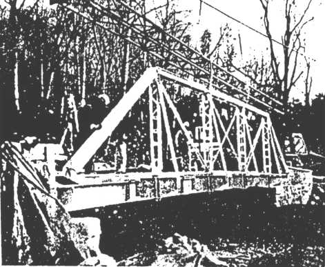
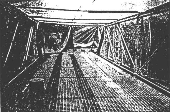
EKKI TIMBER DECK AND BRIDGE RAIL
To complete the project, the approach roadways were reconstructed according to PA DOT criteria; and surrounding property was graded and seeded. Chester County Bridge #65 was reopened to traffic February 8, 1993. Although the bridge is posted for twenty tons and as a one lane bridge, it will serve anticipated traffic at this location for many years. The reconstruction project has upgraded the hydraulic and structural capacity of bridge, added safety features, and reconditioned the original members while maintaining the historical and aesthetic significance of the bridge and its surroundings.
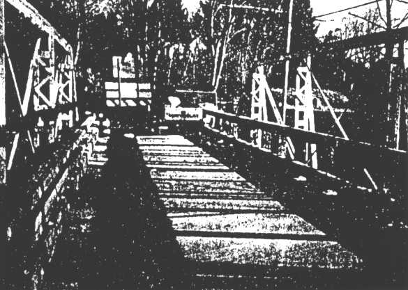
ELEVATION OF REHABILITATED BRIDGE